UDN
Search public documentation:
TerrainDesign
日本語訳
中国翻译
한국어
Interested in the Unreal Engine?
Visit the Unreal Technology site.
Looking for jobs and company info?
Check out the Epic games site.
Questions about support via UDN?
Contact the UDN Staff
中国翻译
한국어
Interested in the Unreal Engine?
Visit the Unreal Technology site.
Looking for jobs and company info?
Check out the Epic games site.
Questions about support via UDN?
Contact the UDN Staff
UE3 Home > Terrain System > Terrain Design: Guidelines and Information
Terrain Design: Guidelines and Information
Overview
 Terrain Creation
Terrain is typically created using one of two techniques: hand-painting directly on the terrain mesh to create the hills and valleys; or importing externally created terrain heightmaps. Additionally, heightmap information can be acquired from DEMs - Digital Elevation Model information. Material layers that represent dirt, grass and rock can be created using terrain alphamaps that determine where the texture is blended onto the terrain.
Terrain Use and Map Layout
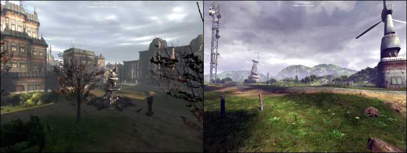
Terrain can be used for small areas such as city lots, enclosed courtyards and even to simulate piles of debris; or the entire game map may be based on a large outdoor terrain design that incorporates a variety of geological features such as mountains and valleys.
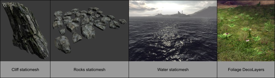
The terrain is often used in conjunction with specifically-designed geological meshes for large boulders, buttes, cliffs, and even water planes. Additional meshes are also used for the various foliage that may appear on the terrain. Map designs and layouts using terrain for video games will often utilize the terrain's ability to create impassable mountains or cliffs around the circumference of the play area, in order to restrict the movement of the game player and prevent them from leaving or falling off of the game map "world".
The terrain system essentially renders an X*Y array of mesh triangles whose vertex Z value determines the altitude of the triangles at each grid intersection. One of the challenges that level designers face is choosing the appropriate layout and resolution of this terrain mesh in order to provide the best visual quality versus performance setting.
Terrain Creation
Terrain is typically created using one of two techniques: hand-painting directly on the terrain mesh to create the hills and valleys; or importing externally created terrain heightmaps. Additionally, heightmap information can be acquired from DEMs - Digital Elevation Model information. Material layers that represent dirt, grass and rock can be created using terrain alphamaps that determine where the texture is blended onto the terrain.
Terrain Use and Map Layout
Terrain can be used for small areas such as city lots, enclosed courtyards and even to simulate piles of debris; or the entire game map may be based on a large outdoor terrain design that incorporates a variety of geological features such as mountains and valleys.
The terrain is often used in conjunction with specifically-designed geological meshes for large boulders, buttes, cliffs, and even water planes. Additional meshes are also used for the various foliage that may appear on the terrain. Map designs and layouts using terrain for video games will often utilize the terrain's ability to create impassable mountains or cliffs around the circumference of the play area, in order to restrict the movement of the game player and prevent them from leaving or falling off of the game map "world".
The terrain system essentially renders an X*Y array of mesh triangles whose vertex Z value determines the altitude of the triangles at each grid intersection. One of the challenges that level designers face is choosing the appropriate layout and resolution of this terrain mesh in order to provide the best visual quality versus performance setting.
 Terrain Size
Unreal Engine 3 supports a maximum world size of 512k x 512k (524288 x 524288) Unreal Units. This is equivalent to approximately 10 kilometers squared of area using the default engine unit conversion of 1 UU = 2 cm (10km x 10km). The actual size of the game play area is usually much less than this, often less than 1 square kilometer for outdoor terrain-based maps. Note that geometry, such as sky spheres, placed outside of the maximum world size will still render, but "world" geometry is limited to this total available area.
The terrain heightmap XY resolution as set by the Terrain.NumPatches, ie. 128x128 or 256x256, and the Display.DrawScale which specifies the size of each terrain patch, ultimately determine the total area of the final terrain mesh. Choosing the most effective set of values for patch size and number of patches is required to obtain the best balance between terrain detail and rendering performance.
It is not recommended to create a terrain larger than 1024x1024 patches for both performance and file size reasons. For example, a 2048x2048 terrain, which is 8 million triangles, is slow to work with in the editor and results in a very large map file size. In most cases even exceeding a 512x512 terrain can lead into certain technical issues, and the map design should be examined and possibly re-evaluated as to whether using such a large terrain is a proper choice.
Heightmap Bit-Depth
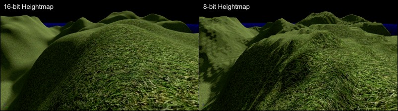
When developing maps with external heightmap files for importing into the Unreal Engine terrain system, always work with the proper 16-bit heightmap format and files. Choosing to work with 8-bit grayscale heightmap files for ease of support in standard paint software results in terrains that are using only 1/256th of the available altitude range. This normally causes an undesirable stair-stepped terracing look to the terrain.
When working with external heightmap files, it is not recommended to attempt to paint detail on the heightmap using standard paint software, as it can only edit and display 8-bits of grayscale on current video hardware. This means that for every single color of gray that is painted on an 8-bit display system, there are actually 256 levels of altitude that cannot be shown visually. In other words, on an 8-bit grayscale display, the value 0 (black) is actually the 16-bit values from 0 to 255, 1 is 256 to 511, etc. So there is no visual accuracy to the values that you are painting to.
Terrain Size
Unreal Engine 3 supports a maximum world size of 512k x 512k (524288 x 524288) Unreal Units. This is equivalent to approximately 10 kilometers squared of area using the default engine unit conversion of 1 UU = 2 cm (10km x 10km). The actual size of the game play area is usually much less than this, often less than 1 square kilometer for outdoor terrain-based maps. Note that geometry, such as sky spheres, placed outside of the maximum world size will still render, but "world" geometry is limited to this total available area.
The terrain heightmap XY resolution as set by the Terrain.NumPatches, ie. 128x128 or 256x256, and the Display.DrawScale which specifies the size of each terrain patch, ultimately determine the total area of the final terrain mesh. Choosing the most effective set of values for patch size and number of patches is required to obtain the best balance between terrain detail and rendering performance.
It is not recommended to create a terrain larger than 1024x1024 patches for both performance and file size reasons. For example, a 2048x2048 terrain, which is 8 million triangles, is slow to work with in the editor and results in a very large map file size. In most cases even exceeding a 512x512 terrain can lead into certain technical issues, and the map design should be examined and possibly re-evaluated as to whether using such a large terrain is a proper choice.
Heightmap Bit-Depth
When developing maps with external heightmap files for importing into the Unreal Engine terrain system, always work with the proper 16-bit heightmap format and files. Choosing to work with 8-bit grayscale heightmap files for ease of support in standard paint software results in terrains that are using only 1/256th of the available altitude range. This normally causes an undesirable stair-stepped terracing look to the terrain.
When working with external heightmap files, it is not recommended to attempt to paint detail on the heightmap using standard paint software, as it can only edit and display 8-bits of grayscale on current video hardware. This means that for every single color of gray that is painted on an 8-bit display system, there are actually 256 levels of altitude that cannot be shown visually. In other words, on an 8-bit grayscale display, the value 0 (black) is actually the 16-bit values from 0 to 255, 1 is 256 to 511, etc. So there is no visual accuracy to the values that you are painting to.
 Staying on Grid
The Terrain actor's Advanced.bEdShouldSnap property should always remain checked (true) so that the terrain patches remain on-grid. This in combination with using a power-of-two Display.DrawScale and Display.DrawScale3D.X/.Y results in patches that properly fit onto the grid on all edges.
Once the Terrain actor has been moved into place in the map, be sure to set the Advanced.bLockLocation to checked (true) to lock the Terrain actor and prevent its accidental movement in the editor.
Staying on Grid
The Terrain actor's Advanced.bEdShouldSnap property should always remain checked (true) so that the terrain patches remain on-grid. This in combination with using a power-of-two Display.DrawScale and Display.DrawScale3D.X/.Y results in patches that properly fit onto the grid on all edges.
Once the Terrain actor has been moved into place in the map, be sure to set the Advanced.bLockLocation to checked (true) to lock the Terrain actor and prevent its accidental movement in the editor.
 The Power-of-Two
Often when working with terrain and other game assets, the phrase "power-of-two" will come up. Power-of-two numbers are those that are calculated from the formula 2^n where n is any number from 0 and greater. So 2^0 = 1. 2^1 = 2. 2^2 = 4. 2^3 = 8. 2^4 = 16. etc. Common power-of-two values used for terrain include 1, 2, 4, 8, 16, 32, 64, 128, 256, 512, 1024.
The Power-of-Two
Often when working with terrain and other game assets, the phrase "power-of-two" will come up. Power-of-two numbers are those that are calculated from the formula 2^n where n is any number from 0 and greater. So 2^0 = 1. 2^1 = 2. 2^2 = 4. 2^3 = 8. 2^4 = 16. etc. Common power-of-two values used for terrain include 1, 2, 4, 8, 16, 32, 64, 128, 256, 512, 1024.
Number of Patches
 The specific values that are supported for the NumPatches properties varies depending on the Terrain.MaxTesselationLevel and Terrain.MinTesselationLevel values. For example, whether NumPatches can be 40 or 85 or even 255 or 256 varies by the TesselationLevel value.
If the MaxTesselationLevel and MinTesselationLevel properties are both set to 1, then any arbitrary terrain size between 1 and the maximum supported size can be specified. This will allow for the creation of odd-sized terrains such as 41x79. The drawback to using TesselationLevel values of 1 are that all terrain triangles in the frustum will be rendered without the use of the dynamic distance LOD tesselation optimization system. This may be acceptable for smaller terrain pieces, but for large terrain systems this will have an impact on the rendered framerate of the map.
Note: It is not recommended to create a terrain larger than 1024x1024 patches for both performance and file size reasons. For example, a 2048x2048 terrain which is 8 million triangles, is slow to work with in the editor and results in a very large map file size. In most cases even exceeding a 512x512 terrain can lead into certain technical issues, and the map design should be examined and possibly re-evaluated as to whether using such a large terrain is a proper choice.
The MinTesselationLevel property should normally be set to the default value of 1. If it is set to the same value as the MaxTesselationLevel property, then the result is the same as setting both properties to 1, no tesselation occurs. If the MinTesselationLevel is set to a value such as one half of the MaxTesselationLevel, ie. Min = 2 and Max = 4, then the number of tesselation areas will be less and the further distance terrain will not have increased optimization quads. In other words, a Min:Max of 1:4 results in two optimized distance areas, a Min:Max of 2:4 results in only one optimized distance area.
If the MaxTesselationLevel is set to a value other than 1 to enable the distance LOD optimization system, the values supported by NumPatches is now limited to a multiple of the MaxTesselationLevel value. For example, if MaxTesselationLevel is 4, NumPatches can be 4, 8, 12, 16, 20, 24, ..., etc. If MaxTesselationLevel is 8, NumPatches can be 8, 16, 24, 32, 40, 48, ..., etc. It is highly recommended to use the dynamic distance LOD tesselation optimization, even though this will limit the choice of terrain size to only multiples of the MaxTesselationLevel value.
The specific values that are supported for the NumPatches properties varies depending on the Terrain.MaxTesselationLevel and Terrain.MinTesselationLevel values. For example, whether NumPatches can be 40 or 85 or even 255 or 256 varies by the TesselationLevel value.
If the MaxTesselationLevel and MinTesselationLevel properties are both set to 1, then any arbitrary terrain size between 1 and the maximum supported size can be specified. This will allow for the creation of odd-sized terrains such as 41x79. The drawback to using TesselationLevel values of 1 are that all terrain triangles in the frustum will be rendered without the use of the dynamic distance LOD tesselation optimization system. This may be acceptable for smaller terrain pieces, but for large terrain systems this will have an impact on the rendered framerate of the map.
Note: It is not recommended to create a terrain larger than 1024x1024 patches for both performance and file size reasons. For example, a 2048x2048 terrain which is 8 million triangles, is slow to work with in the editor and results in a very large map file size. In most cases even exceeding a 512x512 terrain can lead into certain technical issues, and the map design should be examined and possibly re-evaluated as to whether using such a large terrain is a proper choice.
The MinTesselationLevel property should normally be set to the default value of 1. If it is set to the same value as the MaxTesselationLevel property, then the result is the same as setting both properties to 1, no tesselation occurs. If the MinTesselationLevel is set to a value such as one half of the MaxTesselationLevel, ie. Min = 2 and Max = 4, then the number of tesselation areas will be less and the further distance terrain will not have increased optimization quads. In other words, a Min:Max of 1:4 results in two optimized distance areas, a Min:Max of 2:4 results in only one optimized distance area.
If the MaxTesselationLevel is set to a value other than 1 to enable the distance LOD optimization system, the values supported by NumPatches is now limited to a multiple of the MaxTesselationLevel value. For example, if MaxTesselationLevel is 4, NumPatches can be 4, 8, 12, 16, 20, 24, ..., etc. If MaxTesselationLevel is 8, NumPatches can be 8, 16, 24, 32, 40, 48, ..., etc. It is highly recommended to use the dynamic distance LOD tesselation optimization, even though this will limit the choice of terrain size to only multiples of the MaxTesselationLevel value.
Draw Scale
 Draw Scale Z
The DrawScale3D.Z property determines the granularity for each terrain mesh vertex position along the z direction (up and down). The lower the DrawScale3D.Z value, the finer the altitude steps. The greater the DrawScale3D.Z value, the larger the altitude steps. Since there is also only 65536 altitude values in total, the DrawScale3D.Z also determines the total altitude range for the terrain.
There is additional information on DrawScale3D.Z included below.
Draw Scale Z
The DrawScale3D.Z property determines the granularity for each terrain mesh vertex position along the z direction (up and down). The lower the DrawScale3D.Z value, the finer the altitude steps. The greater the DrawScale3D.Z value, the larger the altitude steps. Since there is also only 65536 altitude values in total, the DrawScale3D.Z also determines the total altitude range for the terrain.
There is additional information on DrawScale3D.Z included below.
Terrain Patch Size Area
| DrawScale | Patch in UUs | Patch in Meters | Patch in Feet |
|---|---|---|---|
| 64 | 64 uus | 1.28m (128cm) | 4.2ft (50.39 in) |
| 80 | 80 uus | 1.60m (160cm) | 5.25ft (62.99 in) |
| 96 | 96 uus | 1.92m (192cm) | 6.3ft (75.59 in) |
| 112 | 112 uus | 2.24m (224cm) | 7.35ft (88.19 in) |
| 128 | 128 uus | 2.56m (256cm) | 8.4ft (100.79 in) |
| 160 | 160 uus | 3.20m (320cm) | 10.5ft (125.98 in) |
| 192 | 192 uus | 3.84m (384cm) | 12.6ft (151.18 in) |
| 224 | 224 uus | 4.48m (448cm) | 14.7ft (176.38 in) |
| 256 | 256 uus | 5.12m (512cm) | 16.8ft (201.57 in) |
| 288 | 288 uus | 5.76m (576cm) | 18.9ft (226.77 in) |
| 320 | 320 uus | 6.40m (640cm) | 21ft (251.97 in) |
| 352 | 352 uus | 7.04m (704cm) | 23.1ft (277.17 in) |
| 384 | 384 uus | 7.68m (768cm) | 25.2ft (302.36 in) |
| 512 | 512 uus | 10.24m (1024cm) | 33.6ft (403.15 in) |
Terrain Size versus Map File Size
- Empty clean map with Terrain actor and one Directional Light.
- No Terrain Layers.
- Uncooked.
| Heightmap | Triangles | File Size |
|---|---|---|
| 64x64 | 8,192 | 125kb |
| 128x128 | 32,768 | 3.2MB |
| 256x256 | 131,072 | 7.2MB |
| 512x512 | 524,288 | 28.7MB |
| 1024x1024 | 2,097,152 | 110MB |
- Empty clean map with Terrain actor and one Directional Light.
- One 1024x1024 Texture, one Material, one TerrainMaterial, one TerrainLayerSetup.
- Uncooked.
| Heightmap | Triangles | File Size |
|---|---|---|
| 64x64 | 8,192 | 4MB |
| 128x128 | 32,768 | 6.38MB |
| 256x256 | 131,072 | 10.6MB |
| 512x512 | 524,288 | 32.9MB |
| 1024x1024 | 2,097,152 | 118MB |
Terrain Size versus Map Area
| NumPatches | DrawScale | Length in Unreal Units | Meters | Feet |
|---|---|---|---|---|
| 64 | 64 | 4096 uus | 81.92 m | 268.77 ft |
| 64 | 96 | 6144 uus | 122.88 m | 403.15 ft |
| 64 | 128 | 8192 uus | 163.84 m | 537.53 ft |
| 64 | 192 | 12288 uus | 245.76 m | 806.3 ft |
| 64 | 256 | 16384 uus | 327.68 m | 1074.97 ft |
| 64 | 384 | 24576 uus | 491.52 m | 1612.6 ft |
| 64 | 512 | 32768 uus | 655.36 m | 2150.13 ft |
| 128 | 64 | 8192 uus | 163.84 m | 537.53 ft |
| 128 | 96 | 12288 uus | 245.76 m | 806.3 ft |
| 128 | 128 | 16384 uus | 327.68 m | 1074.97 ft |
| 128 | 192 | 24576 uus | 491.52 m | 1612.6 ft |
| 128 | 256 | 32768 uus | 655.36 m | 2150.13 ft |
| 128 | 384 | 49152 uus | 983.04 m | 3225.2 ft |
| 128 | 512 | 65536 uus | 1.3km (1310.72 m) | 4300.26 ft |
| 256 | 64 | 16384 uus | 327.68 m | 1074.97 ft |
| 256 | 96 | 24576 uus | 491.52 m | 1612.6 ft |
| 256 | 128 | 32768 uus | 655.36 m | 2150.13 ft |
| 256 | 192 | 49152 uus | 983.04 m | 3225.2 ft |
| 256 | 256 | 65536 uus | 1.3km (1310.72 m) | 4300.26 ft |
| 256 | 384 | 98304 uus | 1.97km (1966.08 m) | 1.22 miles (6450.39 ft) |
| 256 | 512 | 131072 uus | 2.6km (2621.44 m) | 1.63 miles (8600.52 ft) |
| 512 | 64 | 32768 uus | 655.36 m | 2150.13 ft |
| 512 | 96 | 49152 uus | 983.04 m | 3225.2 ft |
| 512 | 128 | 65536 uus | 1.31km (1310.72 m) | 4300.26 ft |
| 512 | 192 | 98304 uus | 1.97km (1966.08 m) | 1.22 miles (6450.39 ft) |
| 512 | 256 | 131072 uus | 2.62km (2621.44 m) | 1.63 miles (8600.52 ft) |
| 512 | 384 | 196608 uus | 3.93km (3932.16 m) | 2.44 miles (12900.79 ft) |
| 512 | 512 | 262144 uus | 5.24km (5242.88 m) | 3.26 miles (17201.05 ft) |
| 1024 | 64 | 65536 uus | 1.31km (1310.72 m) | 4300.26 ft |
| 1024 | 96 | 98304 uus | 1.97km (1966.08 m) | 1.22 miles (6450.39 ft) |
| 1024 | 128 | 131072 uus | 2.62km (2621.44 m) | 1.63 miles (8600.52 ft) |
| 1024 | 192 | 196608 uus | 3.93km (3932.16 m) | 2.44 miles (12900.79 ft) |
| 1024 | 256 | 262144 uus | 5.24km (5242.88 m) | 3.26 miles (17201.05 ft) |
| 1024 | 384 | 393216 uus | 7.86km (7864.32 m) | 4.89 miles (25801.57 ft) |
| 1024 | 512 | 524288 uus | 10.49km (10485.76 m) | 6.52 miles (34402.1 ft) |
Optimizing Terrain
- Use DrawScale XY values between 256 and 512 and preferably no lower than 128. Values lower than 128 create dense terrain meshes that require a lot of rendering power.
- Make good use of the built-in distance LOD Tesselation feature by setting the Terrain.MinTesselationLevel to 1 and Terrain.MaxTesselationLevel to 4. Disabling the Tesselation feature usually results in more terrain triangles being rendered in the frustum, requiring more rendering power.
- Limit the number of Materials applied to the terrain. The fewer and simpler the Material setup, the faster it will render.
- Hide the terrain triangles that are never visible or are located under other geometry and assets such as CSG brushes or StaticMesh objects. This is accomplished by editing the terrain with the Visibility Tool and clicking on the patches that are to be hidden. The terrain areas that are set hidden must be large enough to have a significant performance increase to be worthwhile, in other words, don't hide one individual patch under each crate or barrel or tree.
Draw Scale XY and Sinking Map Assets
 When creating assets such as CSG (Constructive Solid Geometry) and static meshes for use in maps, it is common practice to scale all assets so that they fit onto the power-of-two grid spacing. If the terrain patches are also scaled to be power-of-two in size, then assets such as static mesh buildings that are sunk into the terrain, will cleanly line up with the edges of the terrain patches, and those patches that are not visible inside or underneath of the sunk asset can often be hidden using the Terrain Visibility Tool for a possible performance increase. If the asset has an interior, such as a building, the patches of terrain that are inside of the building will have to be hidden in order that they do not interfere with the player movement inside of the structure.
Draw Scale Z versus Altitude Range
 Altitude Ranges
The following table lists common DrawScale3D.Z values and the equivalent maximum altitude range that it supports from the lowest to highest heightmap value (0 or black is lowest G16 altitude, 65535 or white is highest G16 altitude). Rarely will the DrawScale3D.Z value be greater than 64 in actual use. If an external G16 heightmap file is imported and it requires a DrawScale3D.Z of more than 64 to 128, the heightmap should be changed so that it is utilizing more of the available 16-bit range so that any editing granularity is finer, and the vertex movement during painting is finer.
The actual ratio is 1:512 where 1 Display.DrawScale3D.Z unit = 512 Unreal Units of total heightmap altitude range.
So divide the desired total Unreal Units altitude range you want by 512 to get the DrawScale3D.Z that you should use.
UUs per step is the maximum altitude range divided by the 16-bit heightmap range of 65536.
1 Unreal Unit = 2cm. 1 foot = 30.48cm or 0.3048 meters. 1 meter = 3.280839895 feet. 1000 meters = 1 kilometer. 5280 feet = 1 mile.
Altitude Ranges
The following table lists common DrawScale3D.Z values and the equivalent maximum altitude range that it supports from the lowest to highest heightmap value (0 or black is lowest G16 altitude, 65535 or white is highest G16 altitude). Rarely will the DrawScale3D.Z value be greater than 64 in actual use. If an external G16 heightmap file is imported and it requires a DrawScale3D.Z of more than 64 to 128, the heightmap should be changed so that it is utilizing more of the available 16-bit range so that any editing granularity is finer, and the vertex movement during painting is finer.
The actual ratio is 1:512 where 1 Display.DrawScale3D.Z unit = 512 Unreal Units of total heightmap altitude range.
So divide the desired total Unreal Units altitude range you want by 512 to get the DrawScale3D.Z that you should use.
UUs per step is the maximum altitude range divided by the 16-bit heightmap range of 65536.
1 Unreal Unit = 2cm. 1 foot = 30.48cm or 0.3048 meters. 1 meter = 3.280839895 feet. 1000 meters = 1 kilometer. 5280 feet = 1 mile. | DrawScale3D.Z | Max Altitude | UU/step | Range in Meters | mm/step | Range in Feet | in/step |
|---|---|---|---|---|---|---|
| 1 | 512 uus | 0.0078125 | 10.24 m | 0.15625 | 33.6 ft | 0.00615" |
| 2 | 1024 uus | 0.015625 | 20.48 m | 0.3125 | 67.19 ft | 0.0123" |
| 4 | 2048 uus | 0.03125 | 40.96 m | 0.625 | 134.38 ft | 0.0246" |
| 8 | 4096 uus | 0.0625 | 81.92 m | 1.25 | 268.77 ft | 0.0492" |
| 16 | 8,192 uus | 0.125 | 163.84 m | 2.5 | 537.53 ft | 0.0984" |
| 24 | 12,288 uus | 0.1875 | 245.76 m | 3.75 | 806.3 ft | 0.148" |
| 32 | 16,384 uus | 0.25 | 327.68 m | 5.0 | 1075.06 ft | 0.197" |
| 48 | 24,576 uus | 0.375 | 491.52 m | 7.5 | 1612.6 ft | 0.295" |
| 64 | 32,768 uus | 0.5 | 655.36 m | 10.0 | 2150.13 ft | 0.394" |
| 80 | 40,960 uus | 0.625 | 819.20 m | 12.5 | 2687.66 ft | 0.492" |
| 96 | 49,152 uus | 0.75 | 983.04 m | 15.0 | 3225.2 ft | 0.591" |
| 112 | 57,344 uus | 0.875 | 1.15km (1,146.88 m) | 17.5 | 3762.73 ft | 0.689" |
| 128 | 65,536 uus | 1.0 | 1.31km (1,310.72 m) | 20.0 | 4300.26 ft | 0.787" |
| 256 | 131,072 uus | 2.0 | 2.62km (2,621.44 m) | 40.0 | 1.63 miles (8600.52 ft) | 1.575" |
| 512 | 262,144 uus | 4.0 | 5.24km (5,242.88 m) | 80.0 | 3.26 miles (17201.05 ft ) | 3.15" |
| 1024 | 524,288 uus | 8.0 | 10.49km (10,485.76 m) | 160.0 | 6.52 miles (34402.1 ft) | 6.3" |
| 2048 | 1,048,576 uus | 16.0 | 20.97km (20,971.52 m) | 320.0 | 13.03 miles (68804.2 ft) | 12.6" |