UDN
Search public documentation:
MaterialExamples
日本語訳
中国翻译
한국어
Interested in the Unreal Engine?
Visit the Unreal Technology site.
Looking for jobs and company info?
Check out the Epic games site.
Questions about support via UDN?
Contact the UDN Staff
中国翻译
한국어
Interested in the Unreal Engine?
Visit the Unreal Technology site.
Looking for jobs and company info?
Check out the Epic games site.
Questions about support via UDN?
Contact the UDN Staff
UE3 Home > Materials & Textures > Material Examples
Material Examples
Overview
Concepts and Techniques
Specularity
Specularity is the highlight created on a surface as a result of the light reflecting off it. In general, the shinier the surface the smaller and brighter the specular highlight will be.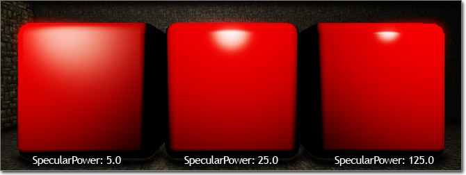 The Specular input channel on the material node is used to control the color and brightness of the specular highlight, while the SpecularPower input channel controls the falloff or tightness of the highlight.
Environment Maps
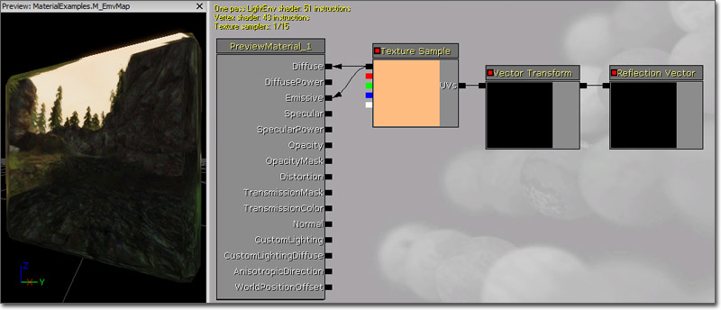
Environment mapping, or reflection mapping, can easily be implemented to apply realtime reflections or to give objects the appearance of reflecting the environment through the use of pre-rendered cubemaps.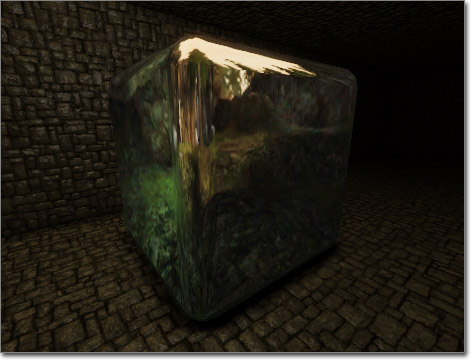 A ReflectionVector expression passed through a Transform (Tangent -> World) is used as the UV texture coordinates for a TextureSample with the environment map assigned. This maps the cubemap (RenderToTextureCube or static cubemap) to the surface of the mesh, causing it to appear reflective.
 The RenderToTexture page has information regarding setting up a SceneCaptureCubeMapActor for realtime reflections as well as using a SceneCaptureCubeMapActor for Saving static captures.
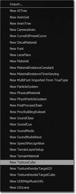
To create a new cubemap manually, right-click in the Content Browser, select New TextureCube from the context menu.
The RenderToTexture page has information regarding setting up a SceneCaptureCubeMapActor for realtime reflections as well as using a SceneCaptureCubeMapActor for Saving static captures.
To create a new cubemap manually, right-click in the Content Browser, select New TextureCube from the context menu.
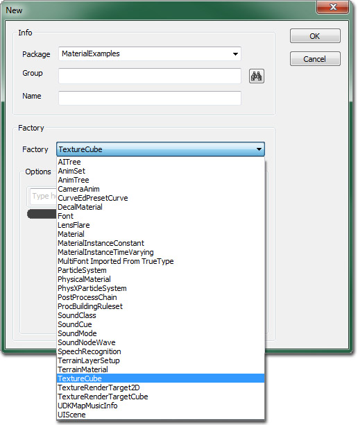
 Another option is to click the New button in the Content Browser and select the TextureCube option in the Factory combobox.
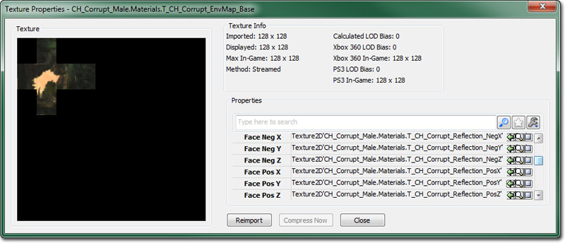
 Then import the six images of your environment and assign them the slots available in the Face Neg/Pos X/Y/Z properties of the new TextureCube. For each of the sides of the CubeTexture, they will be oriented all with the top of the image being the top most part of the texture, and the top and bottom sides will both share the same top direction as depicted in the below image:
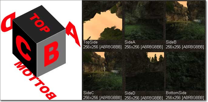 When assigning the textures into the TextureCube, place them in the following slots:
 Once the TextureCube is set up, assign it to a new TextureSample in the Material Editor.
You can connect the RGB output of the TextureSample to the Diffuse input channel of the Material at this point, but you will get errors. To correct these errors you will need to add a new ReflectionVector expression and a new Transform expression. Connect the output of the ReflectionVector to the input of the Transform and then connect the output of the Transform to the UVs input of the TextureSample.
Once the TextureCube is set up, assign it to a new TextureSample in the Material Editor.
You can connect the RGB output of the TextureSample to the Diffuse input channel of the Material at this point, but you will get errors. To correct these errors you will need to add a new ReflectionVector expression and a new Transform expression. Connect the output of the ReflectionVector to the input of the Transform and then connect the output of the Transform to the UVs input of the TextureSample.
Masks
A Mask is a grayscale texture, or a single channel (R, G, B, or A) of a texture, used to limit the area of an effect inside of a material. Quite often, a mask will be contained within a single channel of another texture, such as the alpha channel of the diffuse or normal map. This is a good way to make use of unused channels and keep the number of textures being sampled in the material to a minimum. Technically, any channel of any texture can be thought of and used as a mask. An example mask might look something like the image below: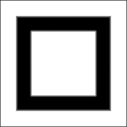 Typical ways to use texture masks include using a Multiply expression to multiply some value by the value of the mask, effectively telling the material to use the value only where the value in the mask is greater than 0.0. This will vary the intensity of the value of the effect based on the mask value.
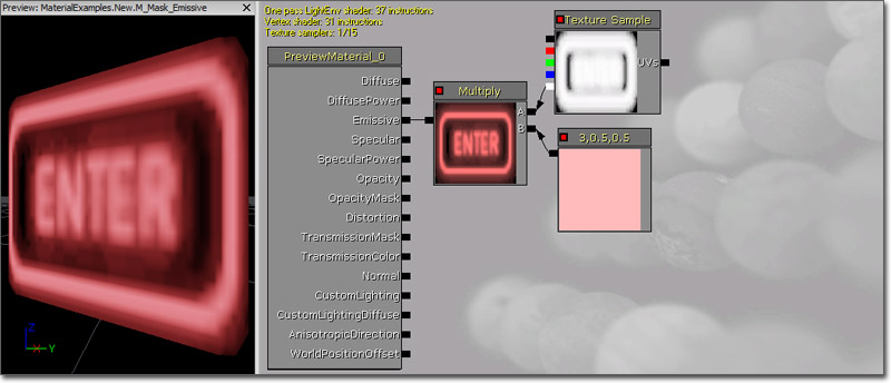
This technique is commonly used with materials that have glowing parts. An Emissive mask is created where the parts that glow are white (or varying shades of gray) while everything else is black. The benefit of this is that it not only allows you to limit where the glow is applied, but you have complete control over the color of the glow inside of the material allowing you to quickly make changes to the color instead of requiring a texture artist to make changes and re-import the texture.
Typical ways to use texture masks include using a Multiply expression to multiply some value by the value of the mask, effectively telling the material to use the value only where the value in the mask is greater than 0.0. This will vary the intensity of the value of the effect based on the mask value.
This technique is commonly used with materials that have glowing parts. An Emissive mask is created where the parts that glow are white (or varying shades of gray) while everything else is black. The benefit of this is that it not only allows you to limit where the glow is applied, but you have complete control over the color of the glow inside of the material allowing you to quickly make changes to the color instead of requiring a texture artist to make changes and re-import the texture.
 Another common use of a mask is to blend between two effects by using the mask as the Alpha input of a LinearInterpolate expression. This will cause one effect or value to be used where the mask is white and another to be used where the mask is black, with a blending of the two in between.
Bump Mapping
In Unreal Engine 3 there are two main techniques used to create Bump Map Materials. Briefly described they are:- Normal Mapping -- Uses XYZ vector information instead of just height info of simple bump maps.
- Offset Bump Mapping -- Virtual height displacement of bumps through modification of texture coordinates in addition to normal mapping.
Normal Mapping
A Normal Map Material uses XYZ information that is stored as RGB components of a texture that is then translated into the surface angle of the texture. This creates the illusion of depth as light reflects off it differently depending on the Normal direction. Creating a material that uses normal mapping is extremely simple in Unreal Engine 3. The first thing that is needed is a normal map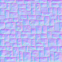 Once you have your normal map imported and ready to use, it needs to be assigned to a TextureSample and then the RGB outputs of that is connected to the Normal input channel of the base Material node.
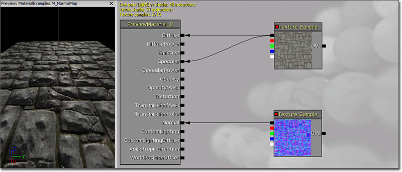 You can clearly see the lighting interacting with the normal mapped surface giving the appearance of having much more detail. The addition of the diffuse texture being connected to the Specular input channel helps illustrate this effect.
Different settings for Normal Map textures
If you are encountering problems with your alpha channel being removed from your normal map or the normal map not giving off the full detail, you can edit the normal map. If you are going to use the offset shader and your height map is in the alpha channel of your normal map, you need to use a different texture compression than TC_NormalMap. Your normal map should be set to TC_NormalMapAlpha so it keeps the alpha channel. This way you can use the parallax bump mapping shader described above. If your normal map isn't reporting the lighting information it should be, you may need to change settings on the normal map itself. This is the result of just importing a common normal map texture without any other editing: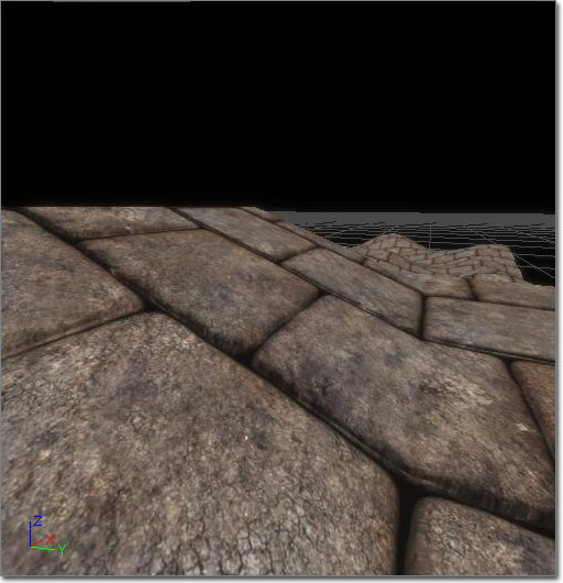 Notice there is not much depth in the texture itself. When applied to a scene with a dynamic light, there are many errors across brush surfaces. After tweaking with the texture in the browser (double click the normal map texture in the Content Browser to bring up the settings window) you can achieve better results.
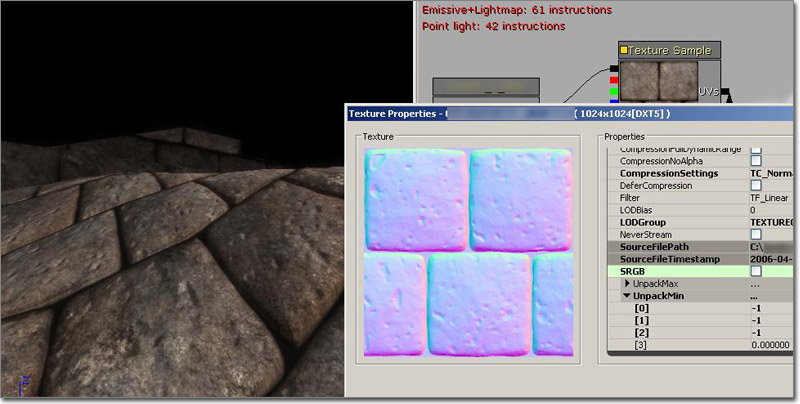 The settings used for a better normal map are listed here. The SRGB check box is not checked. The first 3 channels of UnpackMin set to -1. The LOD Group is - TEXTUREGROUP_WorldNormalMap.
These settings gave the normal map more depth. You will also notice a offset shader is being used. The compression settings on the normal map is set to TC_NormalMapAlpha. The height map is in the alpha channel of the normal map. This is the desired setting for it. Lowering the UnpackMin settings more can give you even more detailed information. If your normal map isn't showing the desired detail, you should try playing with this. However, there are chances of distortion.
The settings used for a better normal map are listed here. The SRGB check box is not checked. The first 3 channels of UnpackMin set to -1. The LOD Group is - TEXTUREGROUP_WorldNormalMap.
These settings gave the normal map more depth. You will also notice a offset shader is being used. The compression settings on the normal map is set to TC_NormalMapAlpha. The height map is in the alpha channel of the normal map. This is the desired setting for it. Lowering the UnpackMin settings more can give you even more detailed information. If your normal map isn't showing the desired detail, you should try playing with this. However, there are chances of distortion.
Offset Bump Mapping
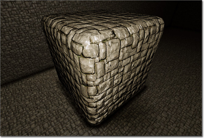
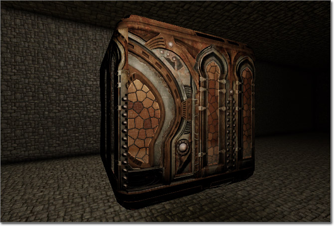
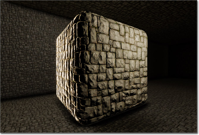
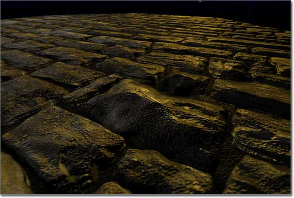 Offset Bump Mapping takes the illusion of depth available in normal maps a step further by appearing to displace the pixels from the surface by modifying the UV coordinates in a creative way. The above screenshot is of a completely flat plane, yet the bricks appear to rise up from the surface, even at this steep angle.
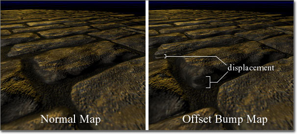
To see the difference between normal maps and offset bump maps look below. Notice the edges of the bricks in the image on the right. The bricks on the left have bumpiness but are essentially flat whereas the bricks on the right appear to have actual height.
Offset Bump Mapping takes the illusion of depth available in normal maps a step further by appearing to displace the pixels from the surface by modifying the UV coordinates in a creative way. The above screenshot is of a completely flat plane, yet the bricks appear to rise up from the surface, even at this steep angle.
To see the difference between normal maps and offset bump maps look below. Notice the edges of the bricks in the image on the right. The bricks on the left have bumpiness but are essentially flat whereas the bricks on the right appear to have actual height.
Heightmap
In addition to the usual assortment of textures you might use in a material (Diffuse, Specular, Normal, etc.), when creating a material using offset bump mapping you will also need a heightmap. The heightmap is a grayscale texture where the shades of gray represent height. In the case of our tutorial, this information is in the alpha channel of a separate texture simply for visualization purposes. In many cases, the heightmap will be contained in the alpha channel of the normal map texture.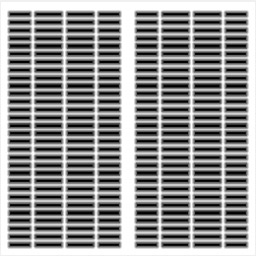
Transmission
Transmission refers to the ability of a surface to pass light through from the opposite side. This effect is similar to what is known as sub-surface scattering (SSS), though it is nowhere near as complex as true SSS.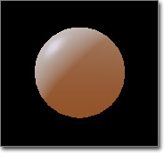 There are two input channels that control the transmission of a material: TransmissionMask and TransmissionColor.
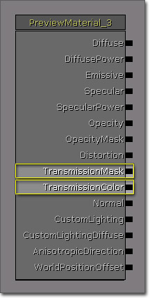 The TransmissionMask input channel can be used by itself or in conjunction with the TransmissionColor, while the TransmissionColor input channel requires a value to be input to the TransmissionMask to function. When passing a value only to the TransmissionMask input channel, the value controls the color and intensity of the transmission. When used in conjunction with the TransmissionColor input channel, the TransmissionMask is multiplied by the TransmissionColor to calculate the total transmission. This means you can pass a color to the TransmissionColor in the form of a Constant3Vector and pass a Constant to the TransmissionMask to use to control the instensity of the transmission.
Edge Lighting
Rim lighting, or edge lighting, is a technique commonly used in film or cinematics where lighting is used to light the silhouette of a character in order to set them apart from the scene or make them the focal point. While this can easily be achieved with normal lights, it requires extra setup and animation to have the lights follow the character. This same basic effect can be done within a material giving greater control over the effect and even using it for other purposes, such as giving a character an ethereal look or simply simulating actual lighting on an unlit surface to save on performance.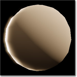
Parameterization
Parameterization refers to the use of parameter expressions within a material. Parameters can be modified by instances of the material or through code. One of the main advantages of parameterization is that you can create a master material which contains all of the functionality you want a collection of materials to all contain. In this master material, certain aspects, such as TextureSamples and key Constants and Constant3Vectors can be replaced with TextureSampleParameter2D, ScalarParameter, and VectorParameter expressions. Then when instances of the master material are created, those aspects of the material can be modified to create completely different materials visually whithout having to waste time or resources creating a new material from scratch. See the InstancedMaterials and MaterialInstanceConstant pages for more information.Examples
Shiny
The examples in this section involve creating surfaces with different types of shininess through the use of Specularity and Environment Maps.Matte
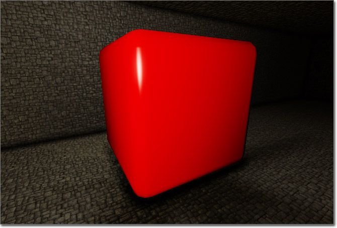
 This surface has a flat appearance, though still having some specular highlight. It can be useful for creating surfaces that do not have much or any gloss to them, such as some plastics and matte painted surfaces.
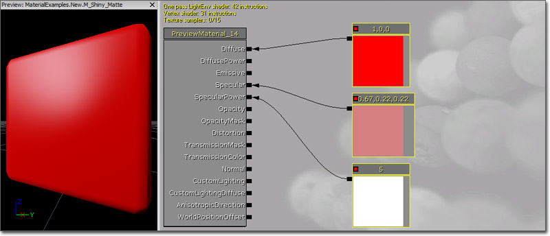 The Diffuse color is a bright red Constant3Vector (1.0, 0.0, 0.0) in the example, but any color or a TextureSample could be used.
The SpecularPower is driven by a Constant with a value of 5.0 causing the highlight to be very dispersed, while the Specular color is a Constant3Vector whose value is a faded version of the Diffuse (0.67, 0.22, 0.22), causes the highlight to be faint.
The Diffuse color is a bright red Constant3Vector (1.0, 0.0, 0.0) in the example, but any color or a TextureSample could be used.
The SpecularPower is driven by a Constant with a value of 5.0 causing the highlight to be very dispersed, while the Specular color is a Constant3Vector whose value is a faded version of the Diffuse (0.67, 0.22, 0.22), causes the highlight to be faint.
Glossy
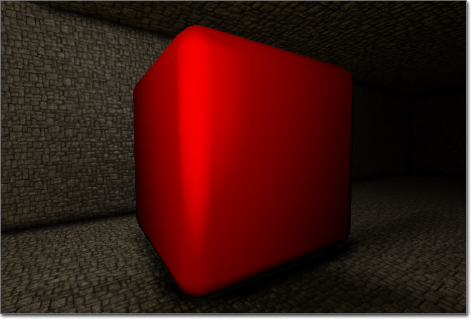
 This surface has a very glossy appearance, with a tight and bright specular highlight. It can be useful for creating any sort of glossy surface, such as glass, polished plastic, car paint, etc.
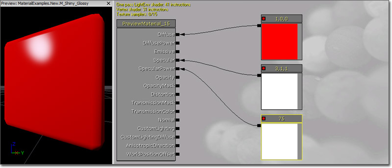 The Diffuse color is a bright red Constant3Vector (1.0, 0.0, 0.0) in the example, but any color or a TextureSample could be used as well.
The SpecularPower is driven by a Constant with a value of 75.0 causing the highlight to be very focused, while the Specular color is a Constant3Vector whose value is an overdriven version of the Diffuse (3.0, 1.0, 1.0) causing the highlight to be bright and pronounced.
The Diffuse color is a bright red Constant3Vector (1.0, 0.0, 0.0) in the example, but any color or a TextureSample could be used as well.
The SpecularPower is driven by a Constant with a value of 75.0 causing the highlight to be very focused, while the Specular color is a Constant3Vector whose value is an overdriven version of the Diffuse (3.0, 1.0, 1.0) causing the highlight to be bright and pronounced.
Metallic
 This surface has a satin appearance, with a fairly dark diffuse color and a dispersed yet fairly bright specular highlight. It can be useful for creating metallic surfaces or satin finishes such as silk fabric.
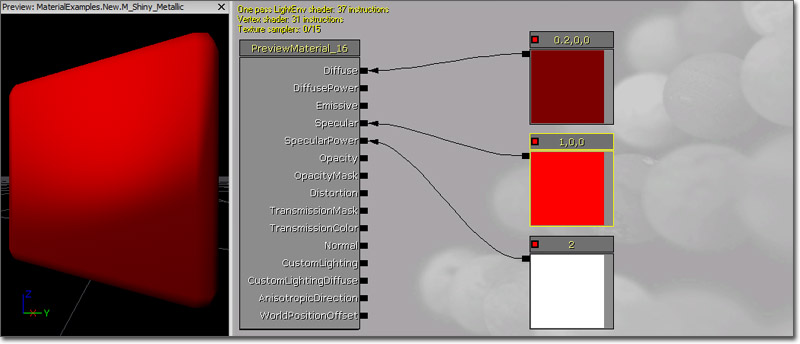 The Diffuse color is a dark red Constant3Vector (0.2, 0.0, 0.0) in the example. Using a darker base color is essential to this effect, as the Specular color is essentially the real color of the surface. If using a TextureSample, you could easily multiply it by a Constant to darken it to achieve a similar effect.
The SpecularPower is driven by a Constant with a value of 2.0 causing the highlight to be very dispersed, while the Specular color is a Constant3Vector whose value is a brighter version of the Diffuse (1.0, 0.0, 0.0) causing the highlight to be bright.
The Diffuse color is a dark red Constant3Vector (0.2, 0.0, 0.0) in the example. Using a darker base color is essential to this effect, as the Specular color is essentially the real color of the surface. If using a TextureSample, you could easily multiply it by a Constant to darken it to achieve a similar effect.
The SpecularPower is driven by a Constant with a value of 2.0 causing the highlight to be very dispersed, while the Specular color is a Constant3Vector whose value is a brighter version of the Diffuse (1.0, 0.0, 0.0) causing the highlight to be bright.
Reflection
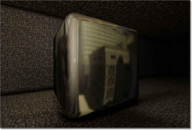 This material uses a cubemap reflection, or environment map, the give the appearance of a polished surface. It can be useful for creating glass, water, chrome, or any other reflective surface.
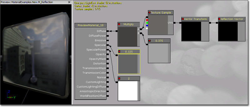 The Diffuse color is controlled by the environment map, which uses a ReflectionVector passed through a Transform (Tangent -> World) for its UV texture coordinates. The environment map is multiplied by a Constant of 0.375 to tone down the reflectivity.
The SpecularPower value of 2.0 causes the highlight to be very dispersed, while the Specular brightness of 0.125 causes the highlight to be faint. This gives a little contrast but keeps the highlight very dim and lets the reflection handle the rest.
The Diffuse color is controlled by the environment map, which uses a ReflectionVector passed through a Transform (Tangent -> World) for its UV texture coordinates. The environment map is multiplied by a Constant of 0.375 to tone down the reflectivity.
The SpecularPower value of 2.0 causes the highlight to be very dispersed, while the Specular brightness of 0.125 causes the highlight to be faint. This gives a little contrast but keeps the highlight very dim and lets the reflection handle the rest.
Bump Offset
To access the heightmap create a new Texture Sample with the texture containing the heightmap assigned to it. If using the alpha channel of the normal map, a duplicate of the TextureSample with the normal map assigned will be needed. Your material network should look something like the one below.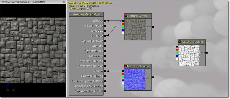 Now add a BumpOffset expression in the workspace (holding B and left-clicking is a quick shortcut) and place it between the heightmap TextureSample and the other TextureSamples in the material. Connect the alpha channel output (bottom one) of the heightmap Texture Sample to the "Height" input of the BumpOffset.
Selecting the BumpOffset expression will display its properties. These should be adjusted to get the desired look for the effect.
Now add a BumpOffset expression in the workspace (holding B and left-clicking is a quick shortcut) and place it between the heightmap TextureSample and the other TextureSamples in the material. Connect the alpha channel output (bottom one) of the heightmap Texture Sample to the "Height" input of the BumpOffset.
Selecting the BumpOffset expression will display its properties. These should be adjusted to get the desired look for the effect.
- HeightRatio - Effectively the ratio between the virtual height of the bumps and the width of the texture. The default is .05, which means that if one tile of the material is mapped to a 10 ft square, the bump depth will appear to be about 10*.05=.5 ft. Find a value that looks right for your material.
- ReferencePlane - A number between 0 and 1 which represents the bump height which results in no texture coordinate offset. The default of .5 should work for most cases. Tweak it if desired.
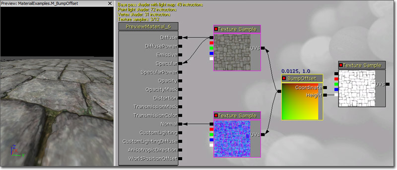 The final material network should look something like the one above. In this case the diffuse material is serving as the material's specular map, which does not have to be the case in your network.
Glow
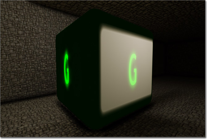 This material uses the Emissive input channel to cause parts of the surface to glow, meaning it will appear fully lit even when no light is affecting it. This effect can be useful for creating lights (i.e., the physical mesh used as the visual representation of a light in the world), particle effects, and any other surface which should appear to give off light. When used in conjunction with Lightmass, the surface itself can actually be used as an area light using the Emissive input channel to give off light.
(Click for full size)
This material uses the Emissive input channel to cause parts of the surface to glow, meaning it will appear fully lit even when no light is affecting it. This effect can be useful for creating lights (i.e., the physical mesh used as the visual representation of a light in the world), particle effects, and any other surface which should appear to give off light. When used in conjunction with Lightmass, the surface itself can actually be used as an area light using the Emissive input channel to give off light.
(Click for full size)
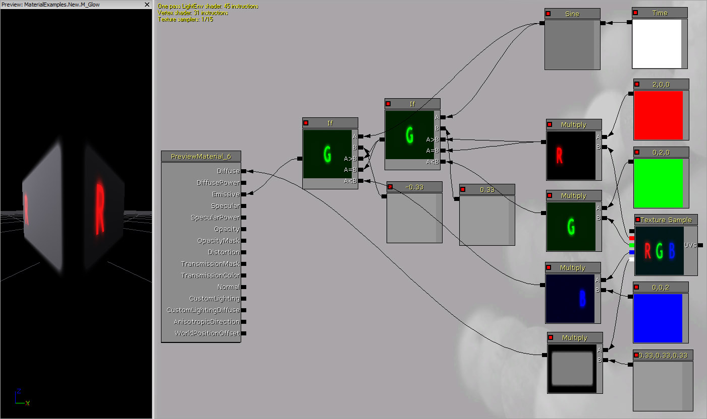 The Diffuse color of the material comes from the Alpha channel of the TextureSample.
The R, G, and B channels of the TextureSample are all used as individual masks which are multiplied by red, green, and blue Constant3Vectors respectively. These are then passed through a series of If expressions which compare the output of a Sine expression to a couple of Constant values in order to alternate between the three colors. The output of the final If expression is connected to the Emissive input channel to produce the glowing letters.
The Diffuse color of the material comes from the Alpha channel of the TextureSample.
The R, G, and B channels of the TextureSample are all used as individual masks which are multiplied by red, green, and blue Constant3Vectors respectively. These are then passed through a series of If expressions which compare the output of a Sine expression to a couple of Constant values in order to alternate between the three colors. The output of the final If expression is connected to the Emissive input channel to produce the glowing letters.
Transparency
These examples use the Opacity or OpacityMask input channels to create transparent materials.Masked Transparency
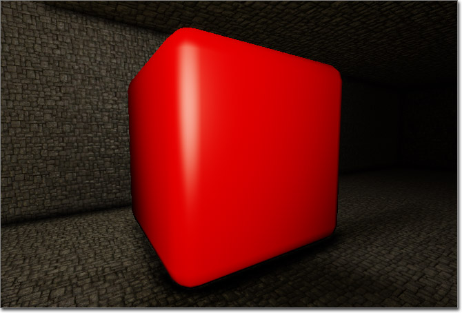
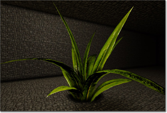 This material uses masked transparency, which means the surface is either completely opaque or completely transparent. This can be used to hide parts of a surface, resulting in the surface appearing more complex than the underlying geometry. For instance, tree or plant leaves and other foliage such as grass commonly use simple planes and use this technique to hide the parts of the mesh outside of the leaf's outline.
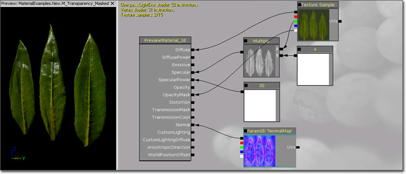 The Diffuse color is driven by a diffuse texture.
The Specular color is obtained from the green channel of the diffuse texture, while the intensity is amplified by multiplying it by a Constant of 4.0.
The Diffuse texture contains the opacity mask in its alpha channel, which is connected to the OpacityMask input channel. Setting the Blend Mode to BLEND_Masked in the material's properties causes the OpacityMask to be used resulting in only the portion of the material where the opacity mask is white (or has a value greater than the Opacity Mask Clip Value to be exact) being visible.
A Normal Map is connected to the Normal input channel to increase the detail of the lighting.
The SoftMasked blend mode results in an effect very similar to this and the setup would be identical.
The Diffuse color is driven by a diffuse texture.
The Specular color is obtained from the green channel of the diffuse texture, while the intensity is amplified by multiplying it by a Constant of 4.0.
The Diffuse texture contains the opacity mask in its alpha channel, which is connected to the OpacityMask input channel. Setting the Blend Mode to BLEND_Masked in the material's properties causes the OpacityMask to be used resulting in only the portion of the material where the opacity mask is white (or has a value greater than the Opacity Mask Clip Value to be exact) being visible.
A Normal Map is connected to the Normal input channel to increase the detail of the lighting.
The SoftMasked blend mode results in an effect very similar to this and the setup would be identical.
Translucency
 This material uses translucency to create surfaces that are not completely transparent or opaque, but with varying degrees of transparency.
(Click for full size)
This material uses translucency to create surfaces that are not completely transparent or opaque, but with varying degrees of transparency.
(Click for full size)
Depth-Based Transparency
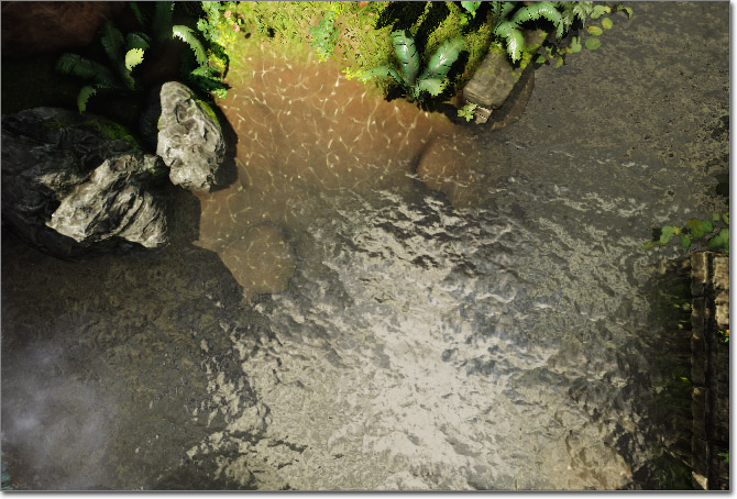 This material demonstrates the use of a depth calculation to vary the transparency of the surface based on how far the surface is from the surface behind it. This is similar to the behavior provided by the DepthBiasAlpha expression only it is completely adjustable. This can be extremely useful when creating water materials as it simulate the natural appearance of water as it nears the shore.
(Click for full size)
This material demonstrates the use of a depth calculation to vary the transparency of the surface based on how far the surface is from the surface behind it. This is similar to the behavior provided by the DepthBiasAlpha expression only it is completely adjustable. This can be extremely useful when creating water materials as it simulate the natural appearance of water as it nears the shore.
(Click for full size)
Refraction
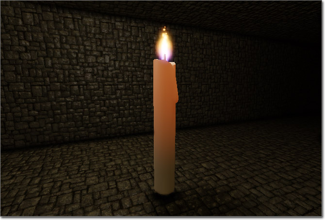
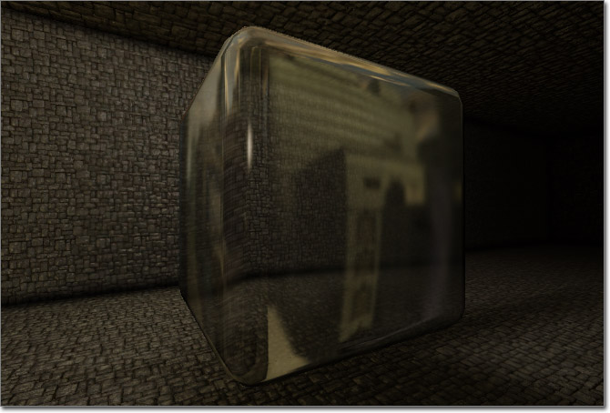 This materials uses transparency and the Distortion input channel to simulate the refraction of light as it passes through the surface. This effect is useful when creating glass or water surfaces as well as particle effects like steam or heat waves.
(Click for full size)
This materials uses transparency and the Distortion input channel to simulate the refraction of light as it passes through the surface. This effect is useful when creating glass or water surfaces as well as particle effects like steam or heat waves.
(Click for full size)
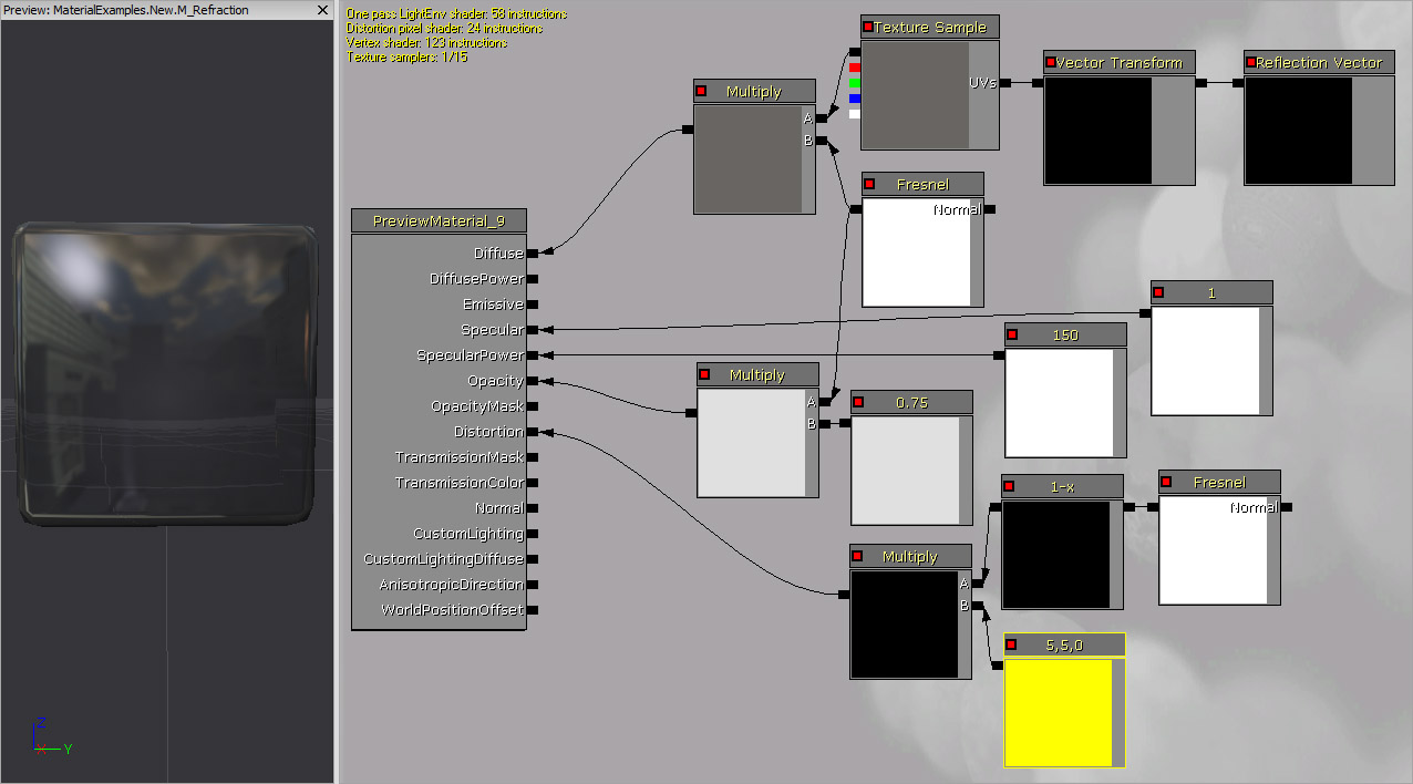 The Diffuse color is driven by an Environment Map multiplied by a Fresnel expression with an Exponent of 0.5 to cause the reflection to gradually become more apparent as the surface faces farther away from the camera.
The SpecularPower is driven by a Constant with a value of 150.0 causing the highlight to be very focused, while the Specular color is a Constant whose value is 1.0 causing the highlight to be fairly bright.
The Opacity is controlled by the same Fresnel expression which is multiplied by a Constant of 0.75.
The Distortion input channel value is calculated by multiplying a Constant3Vector with a value of (5.0, 5.0, 0.0) by a Fresnel with an Exponent of 1.0.
The Diffuse color is driven by an Environment Map multiplied by a Fresnel expression with an Exponent of 0.5 to cause the reflection to gradually become more apparent as the surface faces farther away from the camera.
The SpecularPower is driven by a Constant with a value of 150.0 causing the highlight to be very focused, while the Specular color is a Constant whose value is 1.0 causing the highlight to be fairly bright.
The Opacity is controlled by the same Fresnel expression which is multiplied by a Constant of 0.75.
The Distortion input channel value is calculated by multiplying a Constant3Vector with a value of (5.0, 5.0, 0.0) by a Fresnel with an Exponent of 1.0.
Sub-Surface Scattering
 This material uses the Transmission input channels to simulate a sub-surface scattering effect. This technique is useful when creating skin, wax, or other types of materials that are not transparent, but that light from the opposite side can show through.
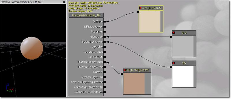 The Diffuse color is being driven by a Constant3Vector, though a TextureSample could be used depending on the material being created.
The SpecularPower is driven by a Constant with a value of 25.0 causing the highlight to be fairly focused, while the Specular color is a Constant whose value is 0.5 causing the highlight to be fairly faint.
The TransmissionMask in the example has a Constant3Vector with a darkened version of the Diffuse color. This could also be a TextureSample as in the Diffuse color.
The Diffuse color is being driven by a Constant3Vector, though a TextureSample could be used depending on the material being created.
The SpecularPower is driven by a Constant with a value of 25.0 causing the highlight to be fairly focused, while the Specular color is a Constant whose value is 0.5 causing the highlight to be fairly faint.
The TransmissionMask in the example has a Constant3Vector with a darkened version of the Diffuse color. This could also be a TextureSample as in the Diffuse color.
Detail
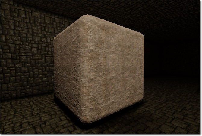 This material combines multiple diffuse and normal maps, one to show larger details at a distance and one to show small details close up. This is commonly used on stone, rock, or concrete materials.
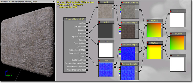 A single TextureCoordinate expression is multiplied by two Constants, one witha value of 0.5 and the other 4.0, to be connected to the UVs inputs of the diffuse and normal maps. The TextureCoordinate multiplied by a value of 0.5 is connected to the UVs input of the diffuse and normal map TextureSamples that will be for the larger, distant details. The TextureCoordinate multiplied by 4.0 is connected to the UVs input of the diffuse and normal map TextureSamples that are used for the small, close up details. The two diffuse TextureSamples are combined using an Add expression and then connected to the Diffuse input channel. The two normal map TextureSamples are combined using another Add expression and connected to the Normal input channel.
The example is for a concrete material so the specular highlight is faint and fairly dispersed.
A single TextureCoordinate expression is multiplied by two Constants, one witha value of 0.5 and the other 4.0, to be connected to the UVs inputs of the diffuse and normal maps. The TextureCoordinate multiplied by a value of 0.5 is connected to the UVs input of the diffuse and normal map TextureSamples that will be for the larger, distant details. The TextureCoordinate multiplied by 4.0 is connected to the UVs input of the diffuse and normal map TextureSamples that are used for the small, close up details. The two diffuse TextureSamples are combined using an Add expression and then connected to the Diffuse input channel. The two normal map TextureSamples are combined using another Add expression and connected to the Normal input channel.
The example is for a concrete material so the specular highlight is faint and fairly dispersed.
Animating UV Coordinates
These examples demonstrate various methods of animating the UV coordinates of textures through the use of Panner and Rotator expressions.Rotating
(Hover for animated preview)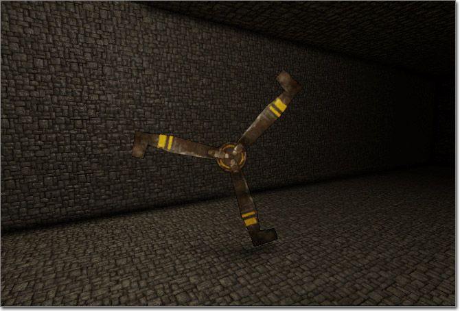
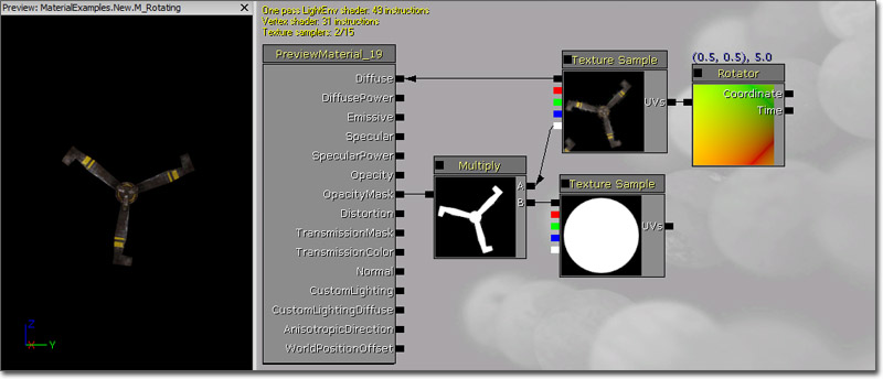 A Rotator with a Speed of 5 is connected to the diffuse TextureSample, whose output is connected to the Diffuse input channel of the material node.
The Alpha channel of the diffuse texture contains the opacity mask. This is multiplied by another mask which is a circle in order to eliminate any extraneous visible parts of the rotating texture (i.e., the corners where the rotating texture wraps around). The result of the Multiply is connected to the OpacityMask input channel and the BLEND_Masked blend mode is used.
A Rotator with a Speed of 5 is connected to the diffuse TextureSample, whose output is connected to the Diffuse input channel of the material node.
The Alpha channel of the diffuse texture contains the opacity mask. This is multiplied by another mask which is a circle in order to eliminate any extraneous visible parts of the rotating texture (i.e., the corners where the rotating texture wraps around). The result of the Multiply is connected to the OpacityMask input channel and the BLEND_Masked blend mode is used.
Panning and Distortion
(Hover for animated preview)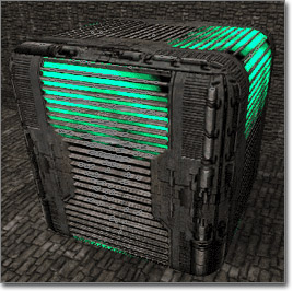
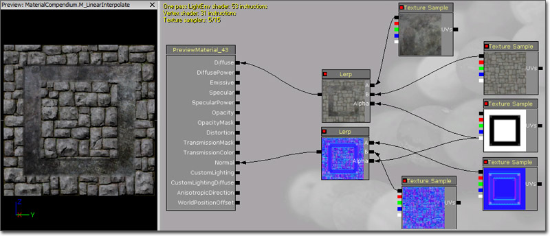
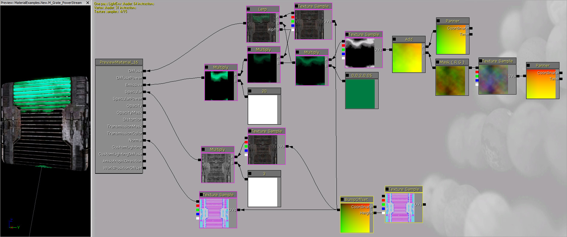 The Diffuse channel is used to create the panning and masked effect as well as to supply the basic texture for the crate. Passed directly into the Diffuse channel is a Linear Interpolate Modifier that combines the panning effect with the grate.
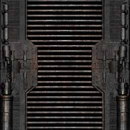 The base grate texture (pictured above) is passed into the A channel of the Linear Interpolate Modifier with a BumpOffset passed into the Coordinates channel of the Texture Sample for the base texture. The BumpOffset is what created the effect of the texture occluding itself.
Into the B channel of the LinearInterpolate is where the panning power stream effect is created. Starting at the very right of the chain of Modifiers is a Panner fed into a rainbow cloud looking TextureSample that causes it to pan in the X direction with a speed of 0.2. Below you can see the texture used in the Texture Sample.
The base grate texture (pictured above) is passed into the A channel of the Linear Interpolate Modifier with a BumpOffset passed into the Coordinates channel of the Texture Sample for the base texture. The BumpOffset is what created the effect of the texture occluding itself.
Into the B channel of the LinearInterpolate is where the panning power stream effect is created. Starting at the very right of the chain of Modifiers is a Panner fed into a rainbow cloud looking TextureSample that causes it to pan in the X direction with a speed of 0.2. Below you can see the texture used in the Texture Sample.
 Then a ComponentMask is applied to pass only the red and green components on into an Add expression. The Add expression is used to add a Panner with SpeedX of 0.0 and SpeedY of 0.2 to the R and G components of the Panning Texture Sample. The result of this Add expression is that it treats the Panner as if it is a texture and adds the color of that Texture to the texture passed into the B channel of the Add expression. This is due to the Material Editor not distinguishing between colors and numbers.
Now, we see the converse effect of a texture being used as a number value as the resulting Add expression is passed into the UVs of a simple Beam Texture. By passing in this complicated series of Modifiers into the UVs of another Sample Texture, the resulting texture is distorted and modified so that it pans with more organic irregularities rippling throughout the texture. Below you can see the contrasting results between the base texture and the texture with all of the Modifiers applied.
Then a ComponentMask is applied to pass only the red and green components on into an Add expression. The Add expression is used to add a Panner with SpeedX of 0.0 and SpeedY of 0.2 to the R and G components of the Panning Texture Sample. The result of this Add expression is that it treats the Panner as if it is a texture and adds the color of that Texture to the texture passed into the B channel of the Add expression. This is due to the Material Editor not distinguishing between colors and numbers.
Now, we see the converse effect of a texture being used as a number value as the resulting Add expression is passed into the UVs of a simple Beam Texture. By passing in this complicated series of Modifiers into the UVs of another Sample Texture, the resulting texture is distorted and modified so that it pans with more organic irregularities rippling throughout the texture. Below you can see the contrasting results between the base texture and the texture with all of the Modifiers applied.
|
|
|
|
|
|
 With all of these chains of Modifiers linked together into the Linear Interpolate Modifier and then passed into the Diffuse channel, the Material will show a grate texture with a dull green organic power stream flowing behind the grate mask.
The Emissive channel is used solely to brighten the green power stream behind the grate mask. To do this, the Multiply Modifier that is passed into the B channel of the Linear Interpolate is also passed into a second Multiply Modifier and multiplied against a Constant. To make the green power stream extra bright, the Constant R value is set at 20.0. Then the resulting Multiply Modifier is passed into the Emissive channel of the Material.
By applying the same base texture via a Sample Texture Modifier into the Specular channel that is used for the grate in the Diffuse Channel, the glare from lights is reduced.
In the Normal channel is just a regular BumpOffset normal map. This creates the effect that the grate actually occludes itself depending on the viewer's eye position. The normal map pictured below is linked into a BumpOffest with the default HeightRatio and ReferencePlane values, and then that BumpOffset is link back into another instance of the normal map as well as the base texture in the diffuse channel. Lastly, the string of normal maps and BumpOffset Modifier is passed into the Normal channel of the final Material.
Here you can see the base normal map used in this material.
With all of these chains of Modifiers linked together into the Linear Interpolate Modifier and then passed into the Diffuse channel, the Material will show a grate texture with a dull green organic power stream flowing behind the grate mask.
The Emissive channel is used solely to brighten the green power stream behind the grate mask. To do this, the Multiply Modifier that is passed into the B channel of the Linear Interpolate is also passed into a second Multiply Modifier and multiplied against a Constant. To make the green power stream extra bright, the Constant R value is set at 20.0. Then the resulting Multiply Modifier is passed into the Emissive channel of the Material.
By applying the same base texture via a Sample Texture Modifier into the Specular channel that is used for the grate in the Diffuse Channel, the glare from lights is reduced.
In the Normal channel is just a regular BumpOffset normal map. This creates the effect that the grate actually occludes itself depending on the viewer's eye position. The normal map pictured below is linked into a BumpOffest with the default HeightRatio and ReferencePlane values, and then that BumpOffset is link back into another instance of the normal map as well as the base texture in the diffuse channel. Lastly, the string of normal maps and BumpOffset Modifier is passed into the Normal channel of the final Material.
Here you can see the base normal map used in this material.
Facing Effects
These examples demonstrate direction-based effects, e.g. effects that are dependent on the direction from which the material is being viewed.Two Tone
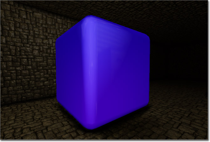 This material simulates a two-tone surface that appears to be one color when viewed from certain directions and another color when viewed from the opposite direction. The surface is also highly Glossy and uses an Environment Map for reflections. This is similar to some car paints.
(Click for full size)
This material simulates a two-tone surface that appears to be one color when viewed from certain directions and another color when viewed from the opposite direction. The surface is also highly Glossy and uses an Environment Map for reflections. This is similar to some car paints.
(Click for full size)
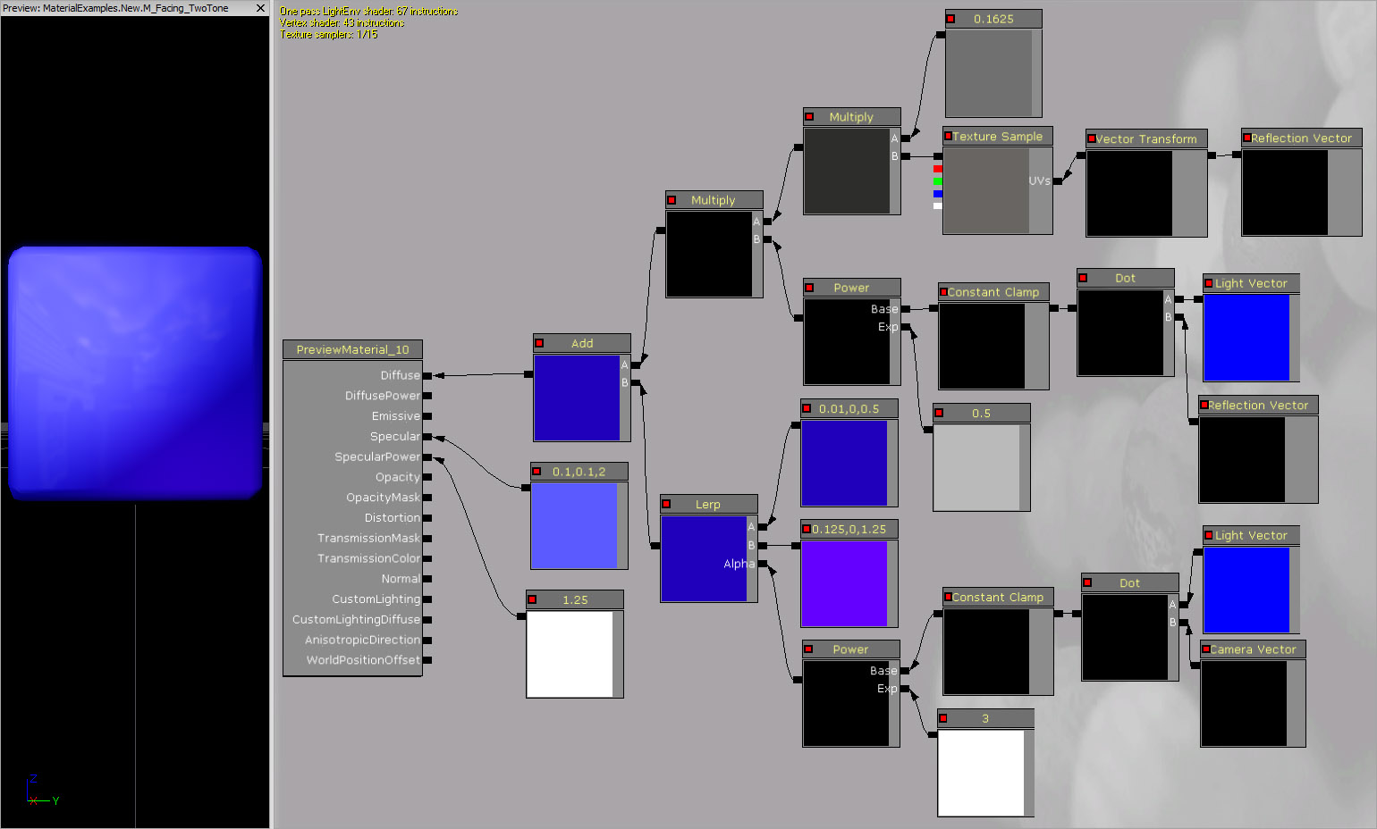 The Diffuse color is a compbination of the two-tone effect and an Environment Map. The Environment Map is multipled by a Constant with a value of 0.1625 to darken it. That is then multiplied by the result of calculation that is similar to the basic Specularity calculation done behind the scenes. A LightVector and a ReflectionVector are passed into a DotProduct. The result is then clamped using a ConstantClamp and passed to a Power as the Base input with an Exp input of 0.5. This entire calculation results in a value of 1.0 when the reflection off the surface points at the light interpolating down to a value of 0.0 when the reflection is perpendicular to the light, which is how Specularity works. This value is then multiplied by the Environment Map.
The two-tone effect uses a similar setup to the reflection effect described above. A LightVector and a ReflectionVector are passed into a DotProduct. The result is then clamped using a ConstantClamp and passed to a Power as the Base input with an Exp input of 3.0. This entire calculation results in a value of 1.0 when the angle the surface is being viewed from is the same as the angle the surface is being lit from interpolating down to a value of 0.0 when viewing the surface perpendicular to the light. This value is used as the Alpha input of a LinearInterpolate expression. The A and B inputs of the LinearInterpolate each have a Constant3Vector connected; one is a deep blue (0.01, 0.0, 0.5) and the other is a brighter blue/purple (0.125, 0.0, 1.25). This will cause the purple color to be applied when viewing the surface from the direction of the light and the blue when viewing the surface perpendicular to the light.
The Environment Map network and the two-tone network are then combined using an Add expression and then connected to the Diffuse input channel of the material node.
The SpecularPower is driven by a Constant with a value of 1.25 causing the highlight to be dispersed, while the Specular color is a Constant3Vector whose value is a slight variation of the purple color (0.1, 0.0, 1.2) causing the highlight to be noticeable, but not overpowering.
The Diffuse color is a compbination of the two-tone effect and an Environment Map. The Environment Map is multipled by a Constant with a value of 0.1625 to darken it. That is then multiplied by the result of calculation that is similar to the basic Specularity calculation done behind the scenes. A LightVector and a ReflectionVector are passed into a DotProduct. The result is then clamped using a ConstantClamp and passed to a Power as the Base input with an Exp input of 0.5. This entire calculation results in a value of 1.0 when the reflection off the surface points at the light interpolating down to a value of 0.0 when the reflection is perpendicular to the light, which is how Specularity works. This value is then multiplied by the Environment Map.
The two-tone effect uses a similar setup to the reflection effect described above. A LightVector and a ReflectionVector are passed into a DotProduct. The result is then clamped using a ConstantClamp and passed to a Power as the Base input with an Exp input of 3.0. This entire calculation results in a value of 1.0 when the angle the surface is being viewed from is the same as the angle the surface is being lit from interpolating down to a value of 0.0 when viewing the surface perpendicular to the light. This value is used as the Alpha input of a LinearInterpolate expression. The A and B inputs of the LinearInterpolate each have a Constant3Vector connected; one is a deep blue (0.01, 0.0, 0.5) and the other is a brighter blue/purple (0.125, 0.0, 1.25). This will cause the purple color to be applied when viewing the surface from the direction of the light and the blue when viewing the surface perpendicular to the light.
The Environment Map network and the two-tone network are then combined using an Add expression and then connected to the Diffuse input channel of the material node.
The SpecularPower is driven by a Constant with a value of 1.25 causing the highlight to be dispersed, while the Specular color is a Constant3Vector whose value is a slight variation of the purple color (0.1, 0.0, 1.2) causing the highlight to be noticeable, but not overpowering.
Rim Lighting
 This material demonstrates the creation of "hard-coded" lighting to create a Edge Lighting effect. A variation of this technique can also be used in unlit materials to simulate lighting, making the material much less intensive to render while still giving the appearance of being lit. Mesh particles sometimes use this effect as they can be expensive to light.
(Click for full size)
This material demonstrates the creation of "hard-coded" lighting to create a Edge Lighting effect. A variation of this technique can also be used in unlit materials to simulate lighting, making the material much less intensive to render while still giving the appearance of being lit. Mesh particles sometimes use this effect as they can be expensive to light.
(Click for full size)
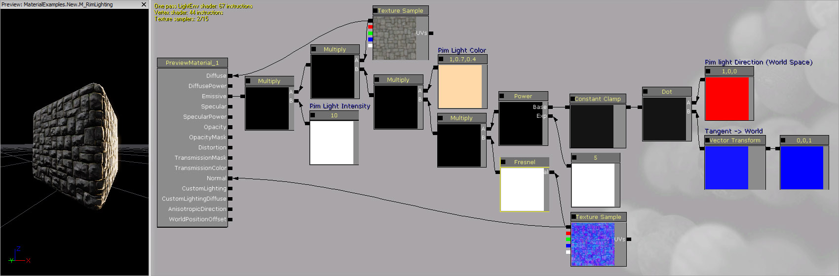 The Diffuse color is simply controlled by a TextureSample.
The Emissive color is driven by the main effect. A Constant3Vector with a value of (0.0, 0.0, 1.0) is transformed from Tangent to World coordinates; essentailly transforming the tangent normal of the surface to a world normal. This is connected to a DotProduct along with another Constant3Vector with a value of (1.0, 0.0, 0.0). The second Constant3Vector represents the light direction. This result of the DotProduct is clamped from [0, 1] and then passed through a Power with a Constant of 5.0 connected to the Exp input. This value controls how much fallow there is for the lighting effect. The result is then multiplies by a Fresnel with an Exponent of 10 and the normal map connected to the Normal input, causing the lighting to only appear around the edge of the mesh even when the lit side is viewed directly. Next, the value is multipled by a Constant3Vector representing the color of the light. Then, the diffuse texture is multiplied in as well. Finally, the value is multipled by a Constant with a value of 10.0 which controls the intensity of the edge lighting. The final result is connected to the Emissive input channel.
The Normals of the surface are controlled by a TextureSample with the normal map applied.
The Diffuse color is simply controlled by a TextureSample.
The Emissive color is driven by the main effect. A Constant3Vector with a value of (0.0, 0.0, 1.0) is transformed from Tangent to World coordinates; essentailly transforming the tangent normal of the surface to a world normal. This is connected to a DotProduct along with another Constant3Vector with a value of (1.0, 0.0, 0.0). The second Constant3Vector represents the light direction. This result of the DotProduct is clamped from [0, 1] and then passed through a Power with a Constant of 5.0 connected to the Exp input. This value controls how much fallow there is for the lighting effect. The result is then multiplies by a Fresnel with an Exponent of 10 and the normal map connected to the Normal input, causing the lighting to only appear around the edge of the mesh even when the lit side is viewed directly. Next, the value is multipled by a Constant3Vector representing the color of the light. Then, the diffuse texture is multiplied in as well. Finally, the value is multipled by a Constant with a value of 10.0 which controls the intensity of the edge lighting. The final result is connected to the Emissive input channel.
The Normals of the surface are controlled by a TextureSample with the normal map applied.
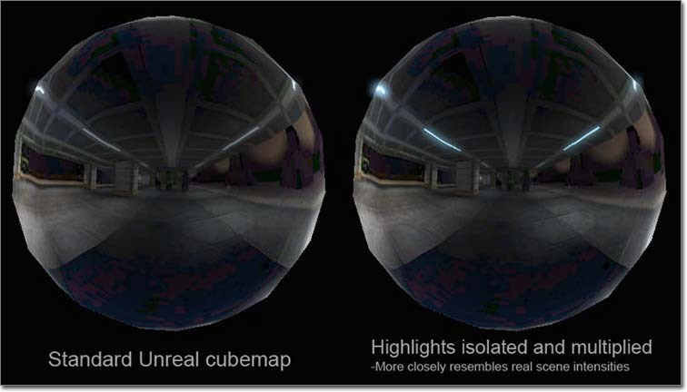
Simulated HDR
 Cube maps with simulated HDR lighting such as the one pictured above, can be easily created with the following modifiers and textures.
 To create the effect, take a cubesample/reflection texture, isolating the brightest pixels, adding a control to modify the intensity of those isolated pixels, and then adds those back on top of the base cubemap. With this setup, the cubemap itself will be darker while still having control over the highlight brightness.
This replicates the behavior of real world reflections: The bright things being reflected stay bright even on translucent or dark surface reflections. For it to look right on cubemaps sampled from within the editor, you'll need to disable the SRGB flag on the cube texture sample. You can leave it off, but you'll get very dark, contrasty reflections.
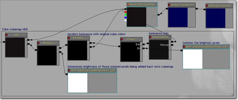
With this approach, you first desaturate the cube texture, isolate the bright pixels from that, then multiply that result with the original cube texture to recolor it before finally adding it to itself. This prevents any wrong color info from being introduced and truly only affects the brightness output.
To create the effect, take a cubesample/reflection texture, isolating the brightest pixels, adding a control to modify the intensity of those isolated pixels, and then adds those back on top of the base cubemap. With this setup, the cubemap itself will be darker while still having control over the highlight brightness.
This replicates the behavior of real world reflections: The bright things being reflected stay bright even on translucent or dark surface reflections. For it to look right on cubemaps sampled from within the editor, you'll need to disable the SRGB flag on the cube texture sample. You can leave it off, but you'll get very dark, contrasty reflections.
With this approach, you first desaturate the cube texture, isolate the bright pixels from that, then multiply that result with the original cube texture to recolor it before finally adding it to itself. This prevents any wrong color info from being introduced and truly only affects the brightness output.
Snow
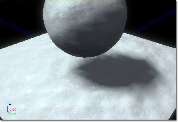 This material simulates a snow material that sparkles.
(Click for full size)
This material simulates a snow material that sparkles.
(Click for full size)
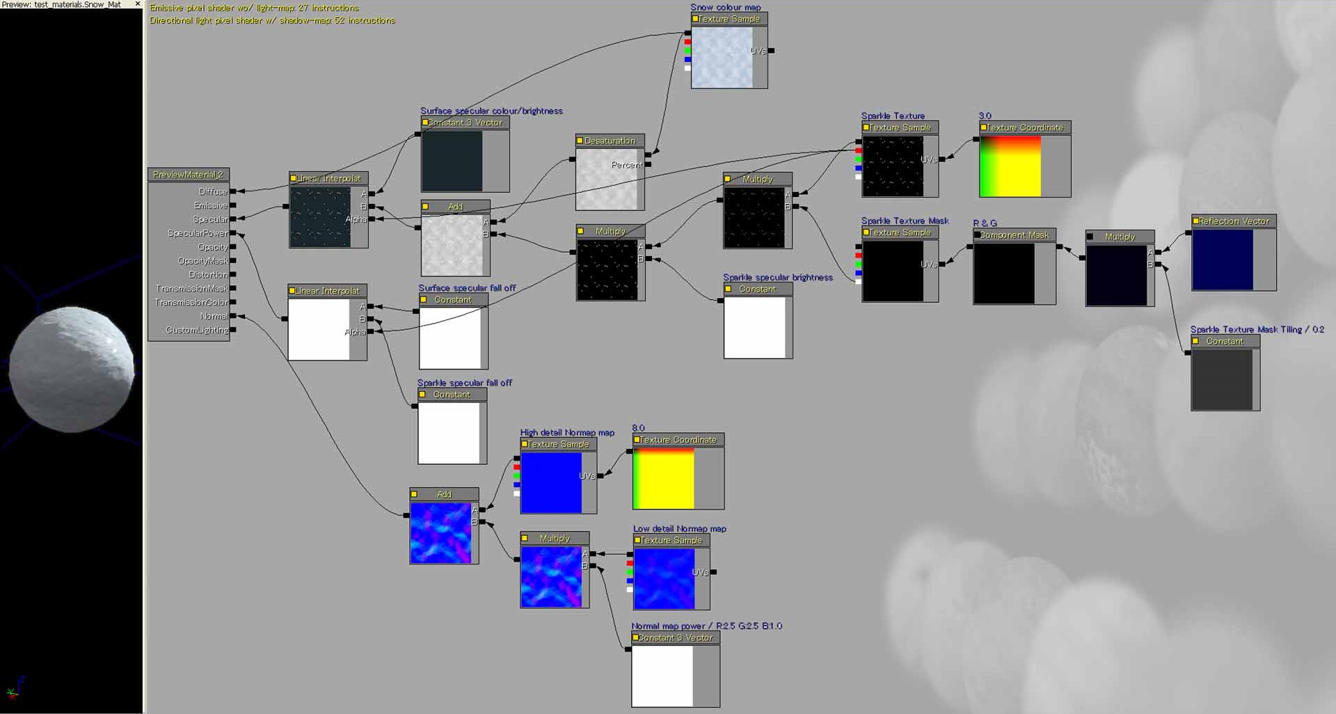 First, create one 512x512 sparkle texture (a black background with dispersed white 1 pixel size dots) in the RBG channel and a mask texture in the Alpha channel to be used as a mask for the sparkling effect (using the Cloud filter in Photoshop and heavily contrasted). Also, if your version of the editor has support for importing DDS textures directly, you can manually create the sparkle texture's mipmap levels to work properly at different distances. The mipmap levels are just a portion of the original sparkle texture cropped and pasted onto the next mipmap level and so forth.
In the Material editor, use a Multiply node to mix both the RGB and Alpha channels (both used as separate nodes with different tiling properties). The RBG channel/node has a standard TextureCoordinate node plugged to it so that you can adjust its tiling. The Alpha channel/node has ReflectionVector through a ComponentMask plugged into it to only use the R and G channels and have a permanent size for the mask regardless the distance. Finally, multiply the Multiply node by a ScalarParameter? so that you can change the sparkle brightness at will.
The main problem is to get the sparkle effect working at different distances. You will see much better results by manually creating mipmaps than using Pixeldepth and the material itself will need less nodes.
First, create one 512x512 sparkle texture (a black background with dispersed white 1 pixel size dots) in the RBG channel and a mask texture in the Alpha channel to be used as a mask for the sparkling effect (using the Cloud filter in Photoshop and heavily contrasted). Also, if your version of the editor has support for importing DDS textures directly, you can manually create the sparkle texture's mipmap levels to work properly at different distances. The mipmap levels are just a portion of the original sparkle texture cropped and pasted onto the next mipmap level and so forth.
In the Material editor, use a Multiply node to mix both the RGB and Alpha channels (both used as separate nodes with different tiling properties). The RBG channel/node has a standard TextureCoordinate node plugged to it so that you can adjust its tiling. The Alpha channel/node has ReflectionVector through a ComponentMask plugged into it to only use the R and G channels and have a permanent size for the mask regardless the distance. Finally, multiply the Multiply node by a ScalarParameter? so that you can change the sparkle brightness at will.
The main problem is to get the sparkle effect working at different distances. You will see much better results by manually creating mipmaps than using Pixeldepth and the material itself will need less nodes.
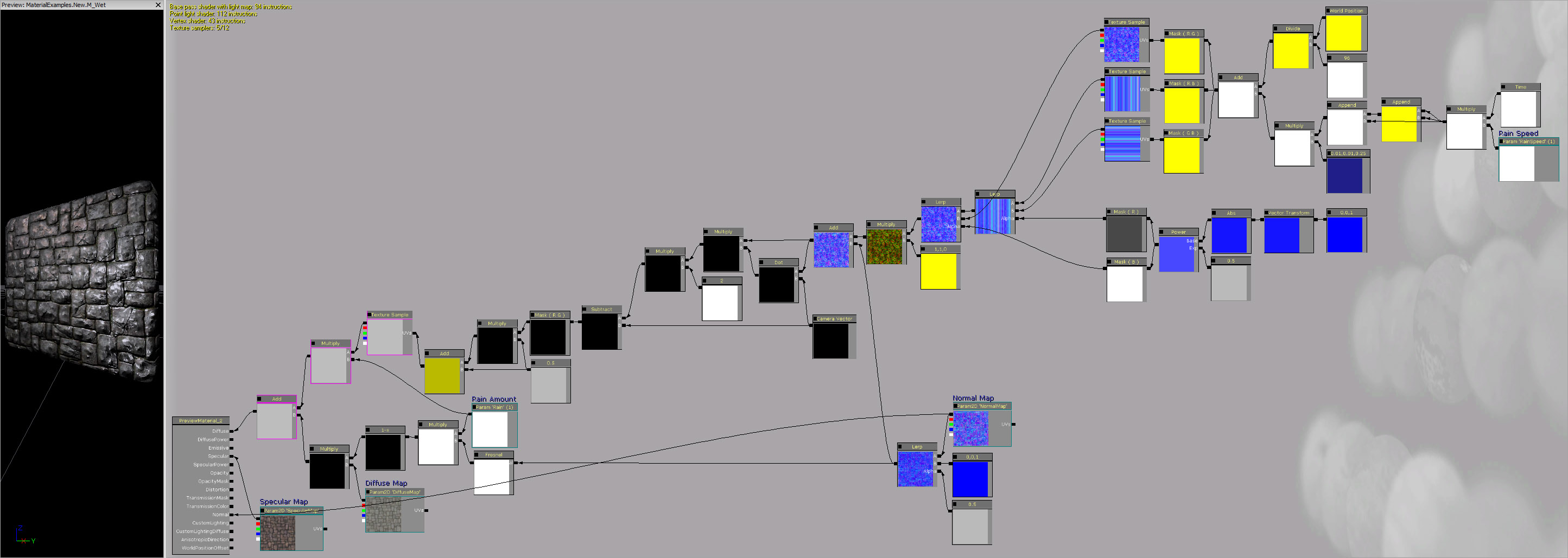
Wet
(Hover for animated preview)